Step 2.2 – Motor Speed Control (part 2 – making a simple circuit)
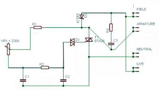
C2 Polyester capacitor 0.047uF 250V (BX74R)
C3 Polyester capacitor 0.01uF VAC
D2 MOV (Metal Oxide Varistor – commonly just referred to as a ‘varistor’) 250VAC (scavenge or e-bay – not sure what the code is)VR1 Variable resistor or POT 220k (FW06G)
R1 Min Resistor 4k7 (M4K7)
R2 Min Resistor 22k (M22K)
R3 Min Resistor 100R (M100R)D1 Diac DB3 (QL08J)
T1 Triac BTA26-600B (UK56L) (the 16A version would suffice – I was in an overkill mood)
Some strip board to put it all on.
Optional components (more on this later):
2X Rectifier J04 (BH46A) ~ £3 each (but I got very similar ones on e-bay for 99p each)
50VA Step down transformer 240V to 9V – (search out old power supplies, audio amps, hi fi’s, etc.)
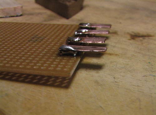
The triac itself can often be salvaged from the washing machines along with the motor. I could have also ordered some spade connectors to make the ‘live’, ‘neutral’, ‘the armature’ and the ‘stator coil’ contacts, but I felt like making my own to save a few pennies (see photo). I used some standard 2mm copper wire scavenged from some old house wiring, and soldered on some cut (using a hacksaw) and flattened (hammer or vice) scrap of copper pipe.

When it comes to actually making the circuit, there is loads of good advice on soldering on instructables, so I will not talk much about that. Enough to say that is is not a complex circuit and it should be pretty straightforwards if you read the instructions here carefully. Thanks to Westfw for the Eagle schematic ‘able (http://www.instructables.com/id/Draw-Electronic-Schematics-with-CadSoft-EAGLE/).

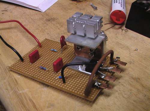
This is the simple chopper circuit made on a piece of stripboard.

June 3rd, 2014 at 2:02 pm
You mention using a lighting dimmer switch to control speed of motor. I have a dimmer that is rated up to 1000 watts. My understanding is that an FHP washing machine motor is less than 1 HP and 1000 watts equates to about 1.3 HP. My project will require the motor to run at about 400 rpm max. but ideally needs the torque and speed not to fluctuate wildly. Do you think the dimmer will achieve this?
Martin.
June 3rd, 2014 at 2:27 pm
Hi Martin,
It is possible but unlikely i’m afraid. Although the rating would seem high enough it may not be, because motors take many times their running current during start up and under heavy load… What’s the application? If the load on the motor is going to vary much, you will not achieve very good speed stability with this technique either…
That said, if you have the dimmer going spare, I might be tempted to try it ;)
May 19th, 2015 at 8:03 pm
Hi guys
Thinking of making this but eBay and our friends in China are advertising some very cheap controllers such as
100% new with high quality
High power controllable silicon
Stable, durable and long lasting
Easy to connect wire and do not need soldering
Size: about 86 x 76 x 37 mm
Specifications:
Max power: 4000W
Input voltage: AC 220V
Voltage regulating range: 60-220V
Functions: 1. Suitable for dimming, regulating speed and temperature
2. Fuse available:
A. When electric appliance is overloaded or cutting-out, the fuse will be burnt out in the shortest time so as to protect electric appliance and controllable silicon;
if the power does not cut off immediately when short circuit happens, you may be in danger of electric shock.
B. When electric appliance is leaking of electricity, the fuse will be burnt out in the shortest time so as to protect the safety of the staff and appliance.
Note: Since the product is series connection product, it needs to increase loads to regulate.
Any good for washing machine motor?
Or can you suggest what sort of spec I should be looking for?
Any help gratefully received.
Looking to make an apple pulper
Kevin
May 20th, 2015 at 11:31 am
Hi Kevin. Sounds like a good project. I’m afraid I don’t have much experience with these kind. I’m quite suspicious – but that’s only because I have no experience and the description is slightly cryptic. If its cheap enough, why not give it a try? Let us know how it works out… Sorry I cant be more help.
May 20th, 2015 at 9:50 pm
Thanks for getting back to me – for the sake of a few pounds will probably give it a go. One other question, I completely understand how to wire up the washing machine mother but how do I remove the small ribbed pulley (not suitable for a V belt), I believe it’s a press or interference fit.
May 20th, 2015 at 10:07 pm
Good question! answer – with great difficulty. Try a gear puller… You have to be careful not to put sideways pressure on the bearings, so a puller is one of the only ways – and even then it will be difficult. I recommend trying to use a poly v belt that fits the current pulley. Let me know how it goes.