Automated door from an old windscreen wiper motor
In this one, we’re making an automatic door for the chicken coop using an old wiper motor some scrap metal, and an Arduino. Before we started keeping chickens we knew we didn’t really want to be tied to getting up at the crack of dawn, or always being at home by dark to put them away. You can get commercial autodoors as pre-made kits to fit on the coop, and indeed we already had experience with one that used a linear actuator – although it was modified so it operated the door to the goose shed (they require a much bigger opening than chickens). Anyway watch the video here, and we’ll give a few extra details below.
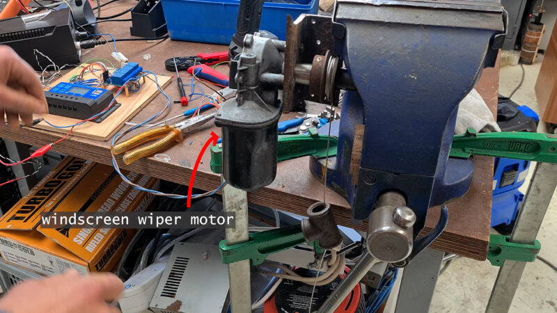
The humble Wiper Motor
Upcycled wiper motors work well for this project because they come with speed-reducing gearing, are very robust, and have ample torque to move a door (even a big heavy door). That, and used ones are plentiful and cheap to get hold of at a scrappy or on e-bay! They are fairly standardized and usually have five wires. Two of these we can ignore for this kind of project (the two you can trace to the gearbox area). The others are a common (the white one in our case), a high, and a lower speed contact.
On the output, most of them, so far as I can tell, come with a tapered splined shaft, that conveniently ends with a male M8 thread. This can be joined to a host of different things. In our case we drilled and tapped an old keyed shaft and v-belt pulley that will form a ‘winding spindle’, to raise and lower the coop door. We happened to have this part but one could just as easily use a wooden spindle, which could be attached with an 8mm pronged insert nut. Another coupling method might be to use an M8 coupling nut (the kind designed for joining 8mm threaded rod).

The Brains
There was a LOT of tweaking to the design, which started off using a relay board to switch the wiper motor, and ended up using a IBT 2 motor driver, as after testing, I deemed even the slower speed of the wiper motor to be too fast. The IBT 2 has the advantage of easily controlling the speed via a pulse width modulation signal from the Arduino. This enables us to easily set the ‘motorSpeed’ in the code, and it lets us easily make the speed much less on the way down (closing) as the way up (opening), to lessen chicken squash risk… It can even smoothly accelerate and decelerate to the selected speed. The only downside is that it makes a bit of a high-pitched noise that’s not super pleasant, but the chickens don’t seem to mind.
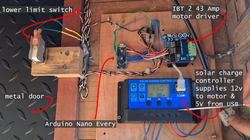
The IBT 2 is a super cheap motor driver module (I got one for less than £5). It uses two BTS7960 half bride chips and comes with a bolt-on heatsink (which I suspect would get very hot if you ran it anything like the claimed 43amps (I’m skeptical of this figure as I have seen identical-looking modules online that claim 30A). The module’s 4 screw terminal connects to the two 12VDC supply wires (from the solar charge controller in my case), and the two wires going to the wiper motor – simple!
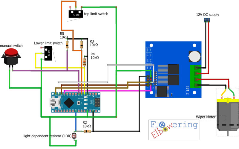
The only other important components are:
- the light dependent resistor (LDR) – which senses the light levels so we can close at dusk and open at dawn. The one I’m using is the GL5516 Light Dependent Resistor Photoresistor which was £2.75 for a pack of 10. I couldn’t find them individually, which as it turns out, was just as well, as I managed to snap the leg off the first one I was using.
- the two limit switches which tell the system if the door is open or closed. They are salvaged from an old microwave (a plentiful source of microswitches).
- a manual switch. This can be activated from outside the coop and is used to manually override, opening or closing the door depending on its current state.
- Four 10KOhm pull-down resistors. I’m fairly sure we could have done without at least 3 of these by using the Arduino’s onboard pull-up facility. There is no internal pull-down, only ‘pull-up’ so that would involve code modifications and I only found out about the possibility when I was mostly finished.
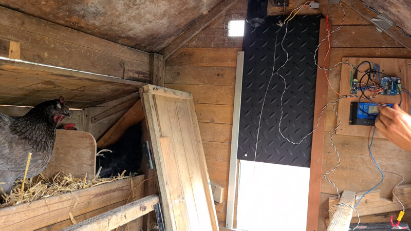
The electronics all get mounted inside the coop out of the elements and get covered over with a wooden box/cover. It’s powered by an old 12V battery (salvaged from a skipped electric wheelchair), which is kept charged with a second hand 20W solar panel, which sits on top of the chickens’ enclosure/run. The solar charge controller that should keep the battery from overcharging is cheap (under£20). I was skeptical, as the battery was already fairly old and tired, but thus far it has seen us through autumn and a Welsh winter without tons of sun…
The Code
I have tried to comment in the code to make it easy to understand, so the best way to get a handle on it is to have a quick look through. It can be downloaded free here on our Ko-fi page.
Here are some highlights though:
The code calibrates the brightness sensor (LDR) by setting the maximum and minimum voltages that correspond to minimum and maximum brightness. It also sets the thresholds for when the door should open and close based on the amount of light detected. This is a percentage value and can be tweaked by adjusting the variables: “brightnessLowThreshold” and “brightnessHighThreshold”.
Hysteresis variables are used to prevent false triggering of the door (say if a shadow, or the beam of a torch, falls across the LDR). The code also sets a timer to ensure that if the limit switch fails for any reason the wiper motor won’t carry on going re-reeling in the wire and opening the door again. If it kept going it would have the potential to damage things…
The setup initializes the pins, while the loop reads the state of the switches and the brightness sensor. It also includes an initialization step to open the door when the system is first turned on. If the door is not in the fully opened position, it will continue to open the door until the limit switch is triggered. The system then measures the brightness and decides whether to open or close the door based on the thresholds set. Finally, the loop includes a manual control button that increments the currentSwitchState variable whenever it is pressed.
Well, that’s about it, the code and circuit diagram are free and on the ko-fi page, any questions please get in touch in the comments on the youtube vid (checked more often than here).
| Tweet |